
Orbit 60 vs 3500: What Changes for Machinery Protection Engineers
What Orbit 60 changes compared with the 3500: architecture, configuration, alarming, self-diagnostics and cybersecurity, and when to choose each platform.

How to set up thrust protection: float zones, two ways to set zero, setpoints from babbitt thickness and five field checks for when the alarm trips.

A thrust bearing failure on a turbine or compressor can turn into a rotor-to-stator rub within seconds. Axial position monitoring is the only protection that sees it coming. But that protection is only as good as its setup: where the probes look, where zero is set, and how the setpoints relate to the actual bearing.
This article walks through the practical side of thrust protection: float zones, the two common methods of setting zero, calculating setpoints from babbitt thickness, and what to check in the field when the thrust alarm goes off.
The thrust bearing holds the rotor in its axial position against the net thrust from the process: steam or gas pressure across the stages, balance piston leakage, coupling forces. The axial clearances in the flow path are often only a few millimetres, and sometimes much less.
Radial bearing problems usually develop over days or weeks and show up in vibration trends. A thrust bearing can fail much faster. Once the babbitt on the active pads is wiped, the rotor moves axially until something else stops it: labyrinth seals, impellers, blades or the diaphragms.
This is why axial position is wired to a shutdown, not just displayed. The goal is to trip the machine after the bearing is damaged but before the rotor contacts the stator. Everything in the rest of this article is about placing that trip point correctly.
Axial position is measured with eddy-current proximity probes mounted parallel to the shaft axis. The probe observes a surface perpendicular to the shaft (the shaft end or an integral collar) and outputs a DC voltage proportional to the gap.
For a standard 8 mm probe system the key numbers are:
Three rules about probe placement matter more than any configuration setting:
If the shaft material differs significantly from 4140 steel, the actual scale factor differs too. This is checked during calibration (see below).
The rotor is free to move axially between the active (loaded) and inactive thrust pads. This total axial clearance is the float zone, and it is the reference for everything else.
The cold float zone is what you measure at standstill: push the rotor against one set of pads, then against the other, and read the travel on a dial indicator. Typical values are in the range of 10 to 20 mils (0.25 to 0.5 mm), but the OEM drawing is the authority.
In operation the picture changes. Under load the rotor sits on the active pads, but the oil film, the pad and the support elastically deflect. Thermal growth of the bearing housing also shifts the pads. The result is the hot float zone: the band within which the rotor actually moves in normal operation. It is typically shifted towards the active side compared with the cold measurement.

Two practical consequences:
The monitor needs a reference point: a rotor position that it displays as zero. Two methods are common in practice. Both work, as long as everyone who reads the screen knows which one was used.
The rotor is pushed fully to one side, then to the other, and the probe gap is set so that the monitor reads zero midway. With a 16 mil (0.4 mm) float, the rotor against the active pads reads +8 mils (0.2 mm) and against the inactive pads reads −8 mils (−0.2 mm).

The rotor is pushed firmly against the active thrust pads, and that position is set as zero. Movement towards the inactive side reads negative, up to the full float value.

The most common field error is not choosing the "wrong" method. It is setting zero with the rotor in an arbitrary position, for example wherever it stopped after shutdown, without pushing it against the pads. The float is then unknown on both sides, and every setpoint built on that zero is wrong by an unknown amount.
Record the method used, the measured float and the gap voltage at zero in the commissioning report. The next engineer will need it.
The probe gap at zero must leave enough linear range in both directions. The rotor has to travel through the full float, plus the wear allowance on each side, plus a margin, without leaving the linear part of the transducer curve.
In practice:
If step 3 does not match, do not adjust the monitor until it does. Check the system on a calibrator (for example a micrometer fixture such as the TK3) with the actual probe, extension cable and Proximitor, ideally on a target of the shaft material. A wrong probe/cable length combination or a non-standard shaft material changes the scale factor, and the protection then trips at the wrong displacement.
Setpoints should be calculated from the bearing, not copied from a default configuration. The logic is simple: start from the position where the rotor rests on the pads, then add the amount of babbitt loss you are prepared to accept before alarm and before trip.
A common rule of thumb is to alarm after about 5 mils (0.13 mm) of babbitt loss and trip after about 10 mils (0.25 mm). The final values must respect two limits from the OEM: the babbitt thickness on the pads and the minimum axial clearance in the flow path. The danger setpoint must always trip the machine before the rotor can reach the stator.
Example: cold float 16 mils (0.4 mm), alarm at 5 mils and danger at 10 mils of babbitt loss, both directions.
Method 1 — zero at the centre of the float zone:
Method 2 — zero at the active side:
The physical trip point is the same with both methods. Only the numbers on the screen differ, which is exactly why the method must be documented.
After the first run at full load, compare the actual operating reading with the active-pad position. If the hot reading already sits a few mils beyond it because of oil film and deflection, review the active-side alarm with the OEM rather than living with a permanently active alarm.
In a BN 3500 system, axial position is typically configured as a thrust position channel on a 3500/42M Proximitor/Seismic monitor. A few settings deserve particular attention:
After configuration, verify each channel end to end: apply a known gap change (or push the rotor) and confirm the reading, the alarm, the relay and the signal in the DCS.
An axial position alarm raises one question first: is the rotor really moving, or is the measurement lying? These checks, in this order, usually answer it.
If checks 1, 3 and 5 all point the same way, treat the reading as real and act on it. Do not raise the setpoints to make the alarm go away.
On steam turbines the two are often confused, but they answer different questions:
They use different probe locations, ranges and setpoints. One cannot replace the other.
Thrust protection works when four things are right: probes on an integral surface close to the bearing, a zero set with the rotor pushed against the pads, setpoints calculated from the actual float and babbitt, and a documented method that every engineer on site understands.
Advance Technology supplies, installs and commissions Bently Nevada vibration monitoring and protection systems for industrial plants across Central and Eastern Europe. Our engineers hold Bently Nevada training certifications. If you need an audit of existing thrust protection settings or commissioning of a new system, contact us.
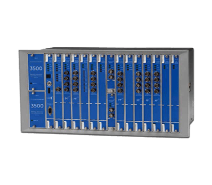
The industry-standard machinery protection system for critical rotating equipment, delivering continuous API 670-compliant monitoring and automatic shutdown protection.
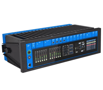
The next-generation Bently Nevada protection and condition monitoring platform, combining protection and prediction in a single cyber-secure system.
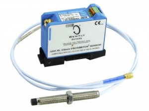
Eddy current probe and Proximitor transducer systems for axial and vibration displacement measurement on large rotating machinery.

Configuration, verification and data-acquisition software tools for setting up, testing and maintaining Bently Nevada 3500 protection racks.
What Orbit 60 changes compared with the 3500: architecture, configuration, alarming, self-diagnostics and cybersecurity, and when to choose each platform.

A practical guide to selecting vibration monitoring: equipment types, criticality assessment, stationary versus portable systems, and integration.

A Bently Nevada case study: why frame vibration alone cannot diagnose a reciprocating compressor, and what cylinder pressure and rod position add.