
Axial Position Monitoring: Setting Up Thrust Protection That Actually Protects
How to set up thrust protection: float zones, two ways to set zero, setpoints from babbitt thickness and five field checks for when the alarm trips.

What we find on Bently Nevada installations at Ukrainian plants: legacy 3300 racks, mixed probe generations, calibration gaps, System 1 Classic, and how to plan a modernisation.

Many Ukrainian plants protect their most critical machines with Bently Nevada systems: turbocompressor trains in nitrogen and ammonia production, steam turbines, gas compressor units and large pumps. A large part of this installed base is 20–30 years old. The systems still trip the machine when they should, but they are getting harder to maintain and give little diagnostic insight.
These notes come from our work on turbocompressor trains in nitrogen production and similar machines. They cover what we typically find, what causes problems, and what to check before planning an upgrade.
It is common to find a 3300 rack, 3300 XL probes on some bearings, older 7200-series probes on others, and extension cables of unknown length. Each generation works on its own, but mixing them causes problems:
What to check: record the part numbers of the probe, cable and proximitor for every channel, and compare them with the rack configuration.
The DC gap voltage tells you where the probe sits relative to the shaft. On older installations we regularly see:
What to check: a gap voltage survey on all channels with the machine stopped and running, compared with installation records. For axial position, confirm the zero against the actual float of the thrust collar.

A protection system that has never been tested since commissioning is an assumption, not protection. The 3500 rack’s self-diagnostics confirm that the electronics and the transducer circuit are working. They do not confirm that the reading is correct. A probe with a drifted scale factor or a wrong cable length will report a plausible but wrong vibration value, with the OK status still green.
On older installations we often find:
A periodic test programme usually covers three levels:
How often: most plants tie testing to planned outages. Transducer and channel checks at every major outage, and a full trip test whenever the protection logic or wiring changes. The exact interval should be defined in the plant’s maintenance programme, not left to memory.
What to check: find the date of the last calibration and the last trip test for each machine. If there is no record, treat the system as unverified and plan the tests for the next outage.
Alarm and danger setpoints are often set to values whose origin nobody remembers. They may have been copied from another machine, changed after a nuisance trip, or taken from the original OEM documentation for a machine that has since been rebuilt.
What to check: compare the current setpoints with OEM recommendations and API 670 guidance, and document the reason for each value. This is also a good moment to review trip logic and voting (e.g. dual voting on radial vibration), because nuisance trips and missed trips both come from here.
System 1 Classic is still in use at many plants. Typical issues:
System 1 Evolution is the current platform. A migration is easiest to plan together with a server replacement or a 3500 upgrade, not as an emergency after a disk failure.
What to check: back up the System 1 configuration and database now, list all OPC and Modbus connections to the DCS, and note which plots and alarms the diagnostic engineers actually use.
A 3300 to 3500 upgrade does not always mean replacing everything:

The main risk is not the hardware but missing information: unknown setpoints, undocumented wiring and unclear trip logic. A site survey before ordering equipment saves time during the outage.
Before a modernisation project on a Ukrainian plant, it helps to prepare:
With this information, an upgrade can be specified accurately, equipment can be ordered once, and site work fits into the planned outage.
Can existing 3300 proximity probes be used with a 3500 system?
Often yes, if the probe, cable and proximitor form a consistent system and are in good condition. This has to be verified channel by channel.
How often should a Bently Nevada protection system be calibrated?
There is no single interval for every plant. A common practice is to verify transducers and monitor channels at each major outage, and to test the full trip path after any change to protection logic or wiring. If the system is part of a SIS, the proof-test interval comes from the SIL assessment.
Is System 1 Classic still worth keeping?
It continues to work, but new development is focused on System 1 Evolution. Plan the migration together with server or rack upgrades.
How is Bently Nevada equipment delivered to Ukrainian plants?
Equipment is usually supplied from the EU, and lead times depend on manufacturer stock. When planning a modernisation, place the equipment request early, before outage dates are fixed, so that delivery does not become the bottleneck of the project.
We work on Bently Nevada systems in Central and Eastern Europe, including Ukraine. If you are planning a modernisation, send us your machine list and we can help with the survey and specification.
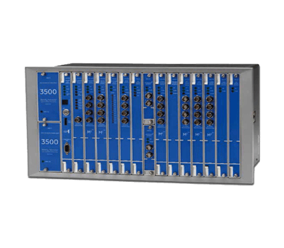
The industry-standard machinery protection system for critical rotating equipment, delivering continuous API 670-compliant monitoring and automatic shutdown protection.
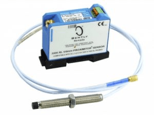
Eddy current probe and Proximitor transducer systems for axial and vibration displacement measurement on large rotating machinery.

Bently Nevada’s enterprise condition monitoring and diagnostics platform for fleet-wide asset health, combining data from online systems, portable devices and process historians.

Configuration, verification and data-acquisition software tools for setting up, testing and maintaining Bently Nevada 3500 protection racks.
How to set up thrust protection: float zones, two ways to set zero, setpoints from babbitt thickness and five field checks for when the alarm trips.

A Bently Nevada case study: why frame vibration alone cannot diagnose a reciprocating compressor, and what cylinder pressure and rod position add.

What Orbit 60 changes compared with the 3500: architecture, configuration, alarming, self-diagnostics and cybersecurity, and when to choose each platform.